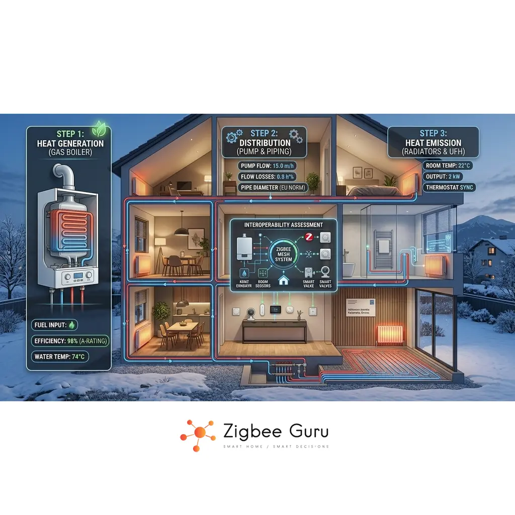
A central heating system is not a single device — it is a chain of four interdependent layers: a source that generates heat, a network that transports it, terminal units that release it into rooms, and a control system that decides when and how much. Every smart thermostat, TRV, or relay you add operates only at the last layer. The rest of the chain must already be correctly designed and commissioned for smart control to make any difference.
This guide covers all four layers in engineering terms that are accessible to any technically minded homeowner or installer. The framework applies universally — whether your system is a condensing gas boiler with panel radiators in Germany, a heat pump with underfloor heating in Scandinavia, or a forced-air furnace in North America. The physics are the same; the hardware conventions differ by region.
If you already know your system architecture and are looking for smart control hardware, jump directly to the Best Zigbee Thermostats for EU Homes guide. If you want to understand the full picture first — including why so many smart heating retrofits underperform — read on.
Table of Contents
- Heat Generation: Sources and Their Control Implications
- The Plant Room: Primary Circuit and Hydraulic Infrastructure
- Heat Distribution: Pipework Topologies and Zone Valves
- Terminal Units: How Heat Enters the Room
- Control Architecture, Zoning, and Equipment
- Control Algorithms and Communication Protocols
- Common System Configurations
- Where Smart Devices Fit in This Architecture
- FAQ
Heat Generation: Sources and Their Control Implications
The heat source defines the operating temperature of your entire system, the control protocols available to you, and the consequences of poor scheduling. A condensing gas boiler tolerates frequent on/off cycling better than an inverter heat pump. A log boiler with no buffer tank cannot be controlled by any smart thermostat because it produces heat on its own schedule. Understanding your source is step one.
Gas and Oil Boilers
A boiler burns fuel to heat water, which is then circulated through the distribution network. The key distinction is between conventional (non-condensing) and condensing boilers. Condensing boilers recover latent heat from flue gases when return water temperature falls below approximately 55°C (131°F), achieving efficiencies above 90%. This only works when the system is designed for low return temperatures — which is one reason mixing valves and weather compensation matter. Oil boilers follow the same hydraulic logic as gas but with different combustion characteristics and fuel storage requirements.
The second distinction is on/off vs modulating burners. A modulating boiler adjusts its heat output continuously between a minimum and maximum firing rate. This is the foundation of OpenTherm and eBUS communication — the thermostat sends a setpoint, and the boiler decides how hard to fire. An on/off boiler simply fires at full rate or not at all, making control logic simpler but less efficient.
Heat Pumps
Air-to-water heat pumps (ASHP) extract heat from outdoor air and deliver it to a hydronic circuit. They are the current EU residential standard for new builds and deep retrofits. Their efficiency (COP) is highest at low supply water temperatures, which is why they are paired with underfloor heating or oversized radiators — not standard-sized panel radiators designed for 70–80°C (158–176°F) water.
Ground-source heat pumps (GSHP) use the earth as a heat source via buried loops or boreholes. They are more efficient than air-source at low outdoor temperatures but have significantly higher installation costs. Air-to-air heat pumps — which are what most North American homeowners call a “heat pump” — do not produce hot water for a hydronic circuit. They heat (and cool) air directly and are outside the scope of this guide’s hydronic sections.
The most critical control implication of any heat pump is the compressor. Inverter (variable-speed) compressors modulate output continuously and perform poorly with frequent start/stop cycles. Control logic for heat pumps must prioritize long, stable run periods over tight setpoint tracking. Short-cycling caused by oversized equipment or aggressive thermostat control is the most common cause of poor heat pump performance.
Hybrid Systems
A hybrid system pairs a heat pump with a gas boiler on the same hydraulic circuit. The heat pump handles the base load at moderate outdoor temperatures; the boiler fires when outdoor temperature drops below the bivalent point — typically between -2°C and +5°C (28–41°F) depending on system sizing. Above the bivalent point, the heat pump is more efficient; below it, the boiler takes over or both run simultaneously. Hybrid control logic is more complex than either source alone and requires a controller that understands both heat sources and outdoor temperature.
Biomass and Solid Fuel
Pellet boilers offer automated fuel feed and modulating output comparable to gas boilers, with similar control options. Log and wood gasification boilers operate differently: combustion is governed by the fuel load, not the control system. A log boiler produces heat on its own schedule, which means the hydraulic system must include a buffer tank large enough to absorb full combustion cycles. Without a buffer, the boiler short-cycles destructively and smart thermostats have no meaningful effect on comfort or efficiency.
Electric Systems
Electric boilers heat water using resistance elements and follow the same hydraulic logic as gas boilers, with simpler control and higher running costs. Direct electric panel heaters and baseboard heaters — common in North America and in individual rooms across Europe — have no hydronic circuit. Each unit is controlled independently, typically with its own thermostat. Electric underfloor heating (resistance cable or mat) belongs in this category: it is electrically simple, straightforward to control per room, and entirely separate from any hydronic system.
Solar Thermal
Solar thermal collectors (flat plate or vacuum tube) pre-heat water using solar energy. They never function as a standalone heat source — they always work alongside a primary source that covers demand when solar yield is insufficient. The control logic is handled by a differential controller that activates the solar pump when collector temperature exceeds storage temperature by a defined threshold. Solar thermal most commonly pre-heats domestic hot water (DHW) and can contribute to space heating in well-designed systems with sufficient storage volume.
District Heating
District heating delivers hot water from a central plant to buildings via insulated underground pipes. It is the dominant system in Scandinavia, much of Germany, and large parts of Eastern Europe. The building-side connection point is a Heat Interface Unit (HIU), which separates the district network from the building’s internal hydronic circuit. From a control perspective, the HIU is your “boiler” — you control demand from the building side; you do not control the generation. For North American readers: district heating exists but is rare outside of urban campuses and some older northeastern cities.
The Plant Room: Primary Circuit and Hydraulic Infrastructure
The plant room is the layer most homeowners and even many installers overlook. It connects the heat source to the distribution network and contains the hydraulic components that determine whether the rest of the system can function correctly. No amount of smart control compensates for a plant room that is poorly designed or missing key components.
Primary vs Secondary Circuit
In many systems, the heat source (primary circuit) is hydraulically separated from the distribution network (secondary circuit). This separation prevents flow interference between the source and the zones — a critical requirement when multiple zones open and close independently. Without separation, zone valve or TRV movements in the secondary circuit can cause flow reversals and instability in the primary circuit.
The separation device is either a low-loss header (hydraulic separator) or a buffer tank. A low-loss header is a small, low-resistance vessel that decouples primary and secondary flow rates. A buffer tank serves the same hydraulic function but also stores thermal energy — essential for log boilers and strongly recommended for heat pumps, where it absorbs short run cycles and reduces compressor starts.
Circulation Pumps
Fixed-speed pumps deliver constant flow regardless of system demand. Variable-speed (ECM/inverter) pumps adjust their output based on differential pressure feedback. When TRVs or zone valves close — as happens constantly in a zoned system — the available flow path decreases. A fixed-speed pump responds by increasing pressure, which can cause noise and accelerated valve wear. A variable-speed pump in ΔP-constant or ΔP-proportional mode reduces speed to maintain design pressure across the open circuits.
This is not an optional upgrade in a system with smart TRVs or motorized zone valves. If you are adding room-by-room control to an existing system, verifying pump type and pressure control mode is a prerequisite — not an afterthought.
Mixing Valves
A mixing valve blends hot supply water with cooler return water to produce a lower supply temperature for a secondary circuit. This is how a single boiler running at 70°C (158°F) can simultaneously supply 70°C to radiators and 35°C (95°F) to underfloor heating circuits. The mixing valve is motorized and driven by an actuator, which in turn receives a signal from a controller. In weather compensation setups, the controller calculates the required supply temperature based on outdoor temperature and drives the mixing valve position accordingly.
Three-way valves blend two inputs into one output. Four-way valves are used in more complex configurations, such as when both heating and cooling circuits share the same secondary network (common with fan coils). Correct valve sizing and actuator selection are a commissioning task — a valve that is oversized or has the wrong authority will hunt and cause instability regardless of the control signal.
Domestic Hot Water (DHW)
DHW is not a separate system — it is a parallel subsystem that shares the heat source with space heating. The control layer must manage the interaction between the two. Most systems implement DHW priority: when the hot water cylinder calls for heat, space heating is temporarily interrupted. This prevents the heat source from being split between two demands simultaneously, which would extend recovery time for both.
Storage configurations range from an indirect cylinder (a tank with an internal coil heated by the boiler) to a plate heat exchanger (instantaneous, common in combi boilers). Heat pump systems almost always use a dedicated DHW cylinder, sized to minimize heat pump cycling during DHW production. An important automation requirement is the legionella protection cycle: a scheduled raise to 60°C (140°F) — typically weekly — to eliminate Legionella bacteria that can colonize lukewarm water storage. This cycle should be a planned automation event, not an afterthought.
Hydraulic Balancing
An unbalanced hydronic system delivers too much flow to near circuits and too little to distant ones. Radiators close to the boiler overheat; radiators at the end of the circuit are cold. No thermostat — smart or otherwise — can correct a flow distribution problem. The correct solution is hydraulic balancing at commissioning: setting lockshield valves on each radiator to achieve design flow rates across all circuits.
Static balancing (preset lockshield valves) works for fixed-flow systems. Dynamic balancing — using differential pressure control valves (DPCVs) or pressure-independent control valves (PICVs) — maintains correct flow regardless of what other zones are doing. PICVs are increasingly common in multi-zone residential systems because they automatically maintain design flow even as TRVs and zone valves open and close. Without some form of balancing, smart zoning at the room level is built on a flawed hydraulic foundation.
Safety Components
Every closed hydronic system requires an expansion vessel to accommodate the increase in water volume as temperature rises, a pressure relief valve set above maximum operating pressure, and air and dirt separators to protect pumps, valves, and heat exchangers from air locks and particulate damage. These are not control components, but their failure causes system shutdowns that no automation platform can prevent. Any smart heating installation in an existing system should verify the condition and sizing of these components as part of the commissioning check.
Heat Distribution: Pipework Topologies and Zone Valves
The distribution network carries hot water from the plant room to the terminal units in each room. Its topology — how pipes are routed and connected — has a direct effect on what kind of control is possible and how much room-by-room independence you can achieve.
Hydronic Pipework Topologies
A single-pipe (one-pipe) system runs a single loop through all radiators in sequence. Each radiator draws hot water from the loop and returns cooler water back into it. The result is that each radiator downstream receives progressively cooler water. Temperature balancing is difficult, and TRVs closing on one radiator affect flow through all downstream radiators. Room-by-room independent control is technically possible but practically limited in single-pipe layouts.
A two-pipe system has a separate supply and return pipe running to each radiator. Every terminal unit receives water at supply temperature, and their return flows independently to the return header. This is the standard topology for modern installations and the correct foundation for independent room control with TRVs or thermostats. Four-pipe systems extend this concept to provide simultaneous heating and cooling to different zones — a dedicated chilled water supply and return run alongside the heating pipes. This is common in commercial buildings and in residential installations with fan coils that serve both heating and cooling functions.
A manifold (radiant) distribution system routes individual circuits from a central manifold to each zone or room. This is the standard arrangement for underfloor heating and is increasingly used for radiator circuits in new residential builds. Each circuit has its own flow and return connection at the manifold, making hydraulic balancing and independent control straightforward.
Motorized Zone Valves
Zone valves provide hydraulic isolation of a circuit or group of circuits based on a control signal. A two-port zone valve opens when its zone thermostat calls for heat and closes when demand is satisfied. A three-port valve diverts flow between two circuits — commonly used to switch between space heating and DHW priority at the boiler. Zone valves are the correct zoning method for large zones (an entire floor, a wing of a house, or a group of fan coils) where individual TRV-level control is either impractical or unnecessary.
Most zone valves include an end switch that closes when the valve reaches its open position. This switch is wired to the boiler and pump controls: the heat source only fires when at least one zone valve is open. This prevents the boiler from running against a fully closed system — a critical safeguard that must be maintained correctly when adding smart relays or automation logic.
Air-Based Distribution (Forced Air)
Air-based systems heat the home by moving heated air through a ductwork network rather than circulating hot water. A gas furnace or air-handler heats air over a heat exchanger or coil, and a fan distributes it through supply ducts to each room. Return air comes back through separate return ducts. This is the dominant residential heating system in North America and is relatively uncommon in European residential buildings, though it is used in commercial construction across both regions.
Control logic for forced-air systems differs fundamentally from hydronic. A single thermostat traditionally controls the entire system because all rooms share the same air stream. Zoning is achieved with motorized dampers in the ductwork, controlled by a zone controller — the air-side equivalent of zone valves. Smart thermostats such as Nest and Ecobee were designed primarily for this architecture: one controller, one heat source, simple on/off or basic modulation. European readers encountering North American smart heating discussions should be aware that most of the advice is written for forced-air systems and does not translate directly to hydronic installations.
Terminal Units: How Heat Enters the Room
Terminal units are the final stage of heat delivery. Their type determines the required supply water temperature, the thermal response speed of the room, and the appropriate control strategy. Choosing smart controls without accounting for terminal unit characteristics is one of the most common causes of poor system performance after a retrofit.
Radiators
Panel radiators emit heat primarily through convection — heated air rises from the panel surface and circulates through the room. Column radiators have higher thermal mass and a slower response. Both require relatively high supply water temperatures, typically 60–80°C (140–176°F) at design conditions, to deliver adequate output at standard sizing. This is the fundamental compatibility issue with heat pumps: a heat pump running at 70°C supply water is operating inefficiently. Retrofitting a heat pump into a radiator system requires either oversizing the radiators, reducing the design outdoor temperature assumption, or accepting lower efficiency.
Hydronic baseboard heaters — common in North American residential buildings — operate on the same hydronic principle as European radiators. Hot water circulates through a fin-tube element enclosed in a baseboard enclosure. They typically require 60–80°C (140–176°F) supply water and are controlled by a room thermostat, often shared across a zone rather than individual to each baseboard.
Fan Coil Units (FCU)
A fan coil unit passes room air over a water coil using a built-in fan. The coil can carry either hot or chilled water, making FCUs capable of both heating and cooling from a single terminal unit. A two-pipe FCU has one set of water connections and can deliver either heating or cooling, but not simultaneously — the system switches between seasons. A four-pipe FCU has separate heating and cooling coils with independent connections, enabling simultaneous heating and cooling in different rooms from the same plant.
Each FCU has its own thermostat that controls a motorized valve on the coil and the fan speed. This makes fan coil systems naturally suited for room-by-room independent control — the control architecture is built into the hardware. FCUs are common in EU Mediterranean climates, hotels, and modern residential retrofits where both heating and cooling are required. They accept a wide range of supply water temperatures, which makes them compatible with both high-temperature boiler systems and heat pumps.
Underfloor Heating — Hydronic
Hydronic underfloor heating (UFH) circulates warm water through pipes embedded in or beneath the floor screed. Heat is delivered by radiation and convection from the large floor surface area. Because the heat transfer surface is large, supply water temperature can be low — typically 30–45°C (86–113°F) — which is exactly the range where heat pumps operate most efficiently. This compatibility makes heat pump plus hydronic UFH the preferred combination for new EU residential builds under current energy regulations.
The significant control challenge of UFH is thermal inertia. The floor screed stores a large amount of heat and takes hours to warm up or cool down. Setpoint changes have delayed effects. Aggressive on/off control causes the floor to overshoot and undershoot comfort temperatures over long cycles. Correct UFH control uses longer time horizons, adaptive start algorithms, and avoids the tight hysteresis bands that work well for radiator systems. TRVs are not used on UFH circuits — flow is controlled by motorized actuators at the manifold, one per circuit.
Actuators in EU residential UFH systems are almost universally 230V, either normally-closed (NC) or normally-open (NO). NC actuators close when de-energized and open when powered — this is the safer default for heating, as a power failure results in circuits closing rather than staying open. In North America, 24V actuators are common. The two voltage classes must never be mixed on the same wiring center. The wiring center aggregates demand signals from room thermostats and drives the appropriate actuators, zone pump, and boiler demand signal.
Underfloor Heating — Electric
Electric UFH uses a resistance cable or mat embedded in the floor. It has no hydronic circuit and is controlled entirely independently of any water-based system. Each room has its own thermostat connected directly to the heating element, making room-by-room control the default rather than an add-on. Electric UFH is practical for bathrooms, small retrofit areas, and isolated rooms where running hydronic pipework is not feasible. Running cost is higher than hydronic because resistance heating has no efficiency multiplier — every kilowatt of electricity produces exactly one kilowatt of heat, unlike a heat pump.
Fan Coil Units and Forced Air (North America)
In North American homes, the terminal unit is most commonly the supply air register — a grille in the floor, wall, or ceiling through which conditioned air enters the room. The central furnace or air handler is the single point of heat production; the ductwork distributes it. Zoning is possible with motorized dampers but is not standard in most residential installations. A single thermostat — increasingly a smart thermostat like Nest or Ecobee — controls the entire system. This is fundamentally different from European hydronic zoning, where independent terminal unit control is the goal.
Other Terminal Units
Natural convectors work like fan coils without the fan — room air circulates by buoyancy through the heated element. They are common in older European buildings, particularly in stairwells and large-glass facades. Radiant ceiling panels circulate water through panels mounted at ceiling level, delivering heat primarily by radiation. They can also carry chilled water for cooling. Towel rails in bathrooms are typically a small, dedicated circuit — often separately valved — and may include an electric backup element for summer use when the main system is off. VRF/VRV systems use refrigerant rather than water as the heat transfer medium; each indoor unit is a terminal unit connected to an outdoor compressor unit via refrigerant lines. They are a separate system category with their own control ecosystems and are outside the scope of this guide.
| Terminal Unit | Required Supply Temp | Heating + Cooling | Control Method | Heat Pump Compatible |
|---|---|---|---|---|
| Panel radiator (standard) | 60–80°C / 140–176°F | Heating only | TRV or room thermostat | Only if oversized |
| Panel radiator (low-temp) | 45–55°C / 113–131°F | Heating only | TRV or room thermostat | Marginal |
| Fan coil unit (2-pipe) | 40–60°C / 104–140°F | Seasonal switch | FCU thermostat + valve | Yes |
| Fan coil unit (4-pipe) | 40–60°C / 104–140°F | Simultaneous | FCU thermostat + valve | Yes |
| Hydronic UFH | 30–45°C / 86–113°F | Heating only* | Room thermostat + actuator | Yes — ideal |
| Electric UFH | N/A (electric) | Heating only | Room thermostat direct | N/A |
| Forced-air register | N/A (air) | Heating + cooling | Central thermostat / dampers | Air-to-air only |
*Hydronic UFH can carry chilled water for cooling in some configurations, but this requires careful dew point management to prevent condensation on the floor surface.
Control Architecture, Zoning, and Equipment
The control system is the layer that smart devices inhabit. Before selecting any hardware, it is necessary to define the control architecture — how many zones you need, how the heat source responds to demand, and what equipment sits between the room sensor and the boiler or heat pump.
System Control Architecture
The simplest architecture is a compact system: one heat source, one zone, one thermostat. The thermostat signals the boiler directly, and heat goes to all terminal units simultaneously. This is still the most common configuration in existing EU residential buildings. It is simple, reliable, and provides no room-level control.
A zoned system adds motorized zone valves, each controlled by a zone thermostat. The boiler fires when any zone calls for heat and the boiler interlock (end switch or demand signal) is satisfied. Primary/secondary separation becomes important here to prevent zone interactions. A primary/secondary with weather compensation system adds a mixing valve that adjusts supply temperature based on outdoor temperature — the boiler or heat pump runs at optimal conditions while the distribution circuit receives the correct temperature for current weather. Cascade systems run multiple heat sources in a lead/lag arrangement: the lead unit runs first; additional units stage on if demand exceeds lead unit capacity. This is common in larger residential buildings and commercial installations.
Zoning Strategy
Zoning level determines how independently different areas of the building are controlled. The levels are:
- Whole-house (Level 0): one thermostat controls all terminal units together. Simple and low-cost; no room-level differentiation.
- By floor or use (Level 1): living areas and bedrooms on separate schedules. Common with zone valves and two thermostats. Meaningful energy savings with minimal complexity.
- Room by room (Level 2): each room has its own temperature setpoint and schedule. Requires TRVs, FCU thermostats, or actuators per room plus a coordination strategy for the heat source.
Room-by-room zoning introduces a coordination problem: what happens when all rooms are satisfied and the boiler is still running? Or when TRVs close but the boiler keeps firing because it has a minimum run time? This is the “open window problem” in reverse — the system must have a strategy for reducing heat source output when zone demand drops. For boilers, this typically means a low-loss header and a bypass circuit. For heat pumps, this is even more important because compressor cycling at low load is damaging.
Control Equipment
Room thermostats measure air temperature and generate a demand signal when temperature falls below setpoint. Wired thermostats are more reliable and do not need battery maintenance; wireless thermostats (including Zigbee, Z-Wave, and 868MHz RF) avoid cable installation and allow flexible placement. Thermostat accuracy and placement matter: a thermostat on an exterior wall, near a window, or close to a heat source will give a misleading room temperature reading and cause poor control.
TRVs (Thermostatic Radiator Valves) control the flow through individual radiators. Mechanical TRVs use a wax or liquid element that expands with temperature to throttle the valve. Electronic TRVs add a motor and a programmable setpoint. Smart TRVs (Zigbee, Z-Wave) add wireless communication and integration with a home automation platform. All TRVs suffer from the same limitation: the temperature sensor is mounted on or near the radiator body, where it reads a temperature significantly higher than the room average. This requires careful offset calibration or the use of a separate room sensor to generate the setpoint command.
Wiring centers (also called zone controllers or heating hubs) aggregate demand signals from multiple room thermostats and drive the correct zone valves, pumps, and boiler demand outputs. In UFH systems, the wiring center also drives individual actuators for each floor circuit. Wiring centers range from simple relay panels with manual connections to smart hubs with wireless thermostat inputs and app-based configuration. The wiring center is the correct place to implement the boiler interlock and pump overrun logic — not in a home automation platform that may restart unexpectedly.
A smart relay replaces or supplements the standard thermostat output to the boiler or heat pump. It receives an on/off command from a home automation platform (via Zigbee, Wi-Fi, or wired) and switches the boiler demand circuit accordingly. This is the standard way to integrate a heat source into Home Assistant or similar platforms without replacing the entire control system.
DHW Control Integration
DHW control must be considered as part of the whole-system control strategy, not a separate afterthought. The cylinder thermostat (or immersion sensor) signals the wiring center or boiler when DHW temperature falls below setpoint. Priority switching — typically wired at the zone valve or wiring center level — ensures the boiler focuses on DHW first. In Home Assistant environments, DHW scheduling can be handled as an automation, but the physical priority interlock should remain in hardware. A software failure that causes both DHW and space heating to demand simultaneously should not be possible by design.
Control Algorithms and Communication Protocols
Once the hardware architecture is defined, the control algorithm determines how the system responds to temperature deviations. The communication protocol determines how control devices talk to each other. Both choices have significant effects on comfort, efficiency, and system longevity.
Control Algorithms
Bang-bang control with hysteresis is the simplest algorithm: if temperature falls below setpoint minus the deadband, turn on; if it rises above setpoint plus the deadband, turn off. A 0.5°C (0.9°F) hysteresis band prevents rapid cycling at the setpoint. Most basic thermostats use this approach. Its limitation is that it produces cyclical temperature swings equal to twice the deadband.
TPI (Time Proportional Integral) is the most common algorithm in EU residential smart thermostats. Rather than switching on/off based purely on temperature, TPI calculates a proportional demand — how much of each cycle period should the heat source be on — based on the temperature error (difference between setpoint and actual temperature) and the accumulated error over time (integral term). The result is that on-time decreases as the room approaches setpoint, reducing overshoot and providing more stable temperature control than bang-bang. Many smart radiator thermostats and wiring centers implement TPI.
PWM (Pulse Width Modulation) applies the same proportional principle at the valve level rather than the source level. An actuator-driven valve opens for a proportion of a fixed cycle period based on the demand signal. This is how many UFH wiring centers control individual circuit actuators — each circuit gets a variable open time within a fixed cycle, allowing proportional heat delivery without modulating the water temperature.
Weather compensation (outdoor reset) is a separate control layer that operates on the heat source, not the room. A weather compensation controller measures outdoor temperature and calculates the required supply water temperature using a heating curve — a linear relationship between outdoor temperature and required supply temperature. As outdoor temperature falls, supply temperature rises. This keeps condensing boilers in condensing mode for longer, improves heat pump COP, and reduces the amplitude of on/off cycling because the system is running at the right temperature for current conditions rather than always at design maximum. Weather compensation operates independently of room thermostats and is one of the highest-impact, lowest-cost improvements available to most existing systems.
Adaptive start algorithms learn how long the system takes to bring a space from setback temperature to comfort temperature, and automatically advance the start time so the room is at setpoint when occupancy begins. This is a scheduling intelligence layer available in many smart thermostats and home automation platforms.
Communication Protocols
The lowest layer is the dry contact (on/off) — a simple voltage-free switch closure that signals “call for heat.” This is how most room thermostats communicate with boilers and how most Zigbee smart relays connect to heat sources. It carries no information beyond on or off, which means the boiler manages all modulation internally based on its own sensors and settings.
OpenTherm is an open, interoperable modulation protocol between a thermostat and a boiler. Instead of an on/off signal, OpenTherm carries a digital message: the thermostat sends a target flow temperature (or boiler setpoint), and the boiler modulates its burner to match. This enables significantly better efficiency from condensing boilers because the boiler can run at the lowest firing rate that satisfies demand, rather than always firing at full rate. OpenTherm is widely supported by European boiler manufacturers (Bosch, Viessmann, Vaillant, Intergas, Remeha, and others) and is available on a growing number of smart thermostats. It is not supported by most Zigbee relay thermostats — OpenTherm requires a dedicated interface.
eBUS is Vaillant and Saunier Duval’s proprietary modulation protocol. It carries more information than OpenTherm but is limited to compatible equipment within those ecosystems. Modbus and BACnet are industrial fieldbus protocols that appear in premium residential heat pump installations and building management systems. They offer extensive data exchange but require more complex integration work. Proprietary manufacturer protocols — such as Viessmann Vitotronic and Buderus Logamatic — provide deep integration within their own ecosystems but limit interoperability with third-party controllers.
The wireless room control layer sits above the wiring and operates between room sensors/thermostats and the home automation platform. Zigbee (IEEE 802.15.4, 2.4 GHz mesh) is currently the leading open protocol for this layer in EU smart homes, offering local operation, mesh networking, and broad Home Assistant support via ZHA and Zigbee2MQTT. Z-Wave operates at 868 MHz in Europe (908 MHz in North America), offering better wall penetration but a smaller device ecosystem. Matter provides application-layer interoperability across IP-based protocols and is increasingly supported by thermostat manufacturers, though hydronic-specific attributes are still maturing in the specification.
Weather compensation and hydraulic balancing together deliver more measurable efficiency improvement than any smart thermostat. Smart devices are the final layer — they depend on everything below being correct.
| Protocol | Type | What it enables | Typical use |
|---|---|---|---|
| Dry contact (on/off) | Wired | Call for heat only | All basic thermostats and relays |
| OpenTherm | Wired (2-wire) | Modulation setpoint, fault codes, efficiency data | EU condensing boilers + compatible thermostats |
| eBUS | Wired (proprietary) | Full boiler data, modulation, DHW control | Vaillant / Saunier Duval systems |
| Modbus / BACnet | Wired (industrial) | Extensive data exchange, integration with BMS | Premium residential, heat pumps, commercial |
| Zigbee | Wireless (2.4 GHz) | Room setpoints, schedules, sensor data | Smart TRVs, wireless thermostats, relays |
| Z-Wave | Wireless (868/908 MHz) | Room setpoints, schedules, sensor data | Smart thermostats, locks, sensors |
| Matter | Wireless (IP-based) | Cross-platform thermostat interoperability | Growing — newer thermostat models |
Common System Configurations
The following scenarios describe the most common real-world combinations of generation, distribution, and emission. Each scenario includes the key control characteristics and the most relevant smart integration approach. Use this section to identify your own system before selecting smart hardware.
| Scenario | Heat Source | Terminal Units | Supply Temp | Key Control Challenge | Smart Integration Approach |
|---|---|---|---|---|---|
| A — Most common EU | Gas boiler | Panel radiators | 60–80°C | Hydraulic balance; no modulation without OpenTherm | Smart relay + Zigbee TRVs per room; OpenTherm if supported |
| B — EU new build (pre-2020) | Gas boiler | Hydronic UFH | 35–45°C | Thermal inertia; wiring center and actuators required | Wireless thermostats per zone + smart relay to boiler |
| C — Current EU new build standard | Air-to-water heat pump | Hydronic UFH | 30–40°C | Avoid short cycling; weather compensation essential | Wireless thermostats + smart relay; conservative scheduling |
| D — Hybrid | Heat pump + gas boiler | UFH or radiators | Variable | Bivalent logic; two sources must coordinate | Manufacturer hybrid controller + smart scheduling layer |
| E — Mediterranean / hotels | Boiler or chiller + heat pump | Fan coil units | 40–60°C / 6–12°C | Heating + cooling seasons; FCU thermostat per unit | Smart FCU thermostat per room; 4-pipe or seasonal switch |
| F — North America primary | Gas furnace | Forced air / registers | N/A (air) | Single-zone by default; duct zoning complex | Smart thermostat (Nest/Ecobee); motorized dampers for zoning |
| G — Small areas / retrofit | Electric resistance | Electric UFH | N/A (electric) | Each room independent by default | Smart thermostat per room; Zigbee or Z-Wave |
| H — Urban EU | District heating HIU | Radiators or FCU | Varies by utility | Cannot control source; demand-side management only | Smart thermostats for demand signaling; HIU settings for schedule |
Scenario A is the correct starting point for the majority of readers with existing EU homes. The gas boiler with panel radiators is the system for which most Zigbee thermostats and TRVs are designed. The smart integration path is well-documented, hardware is widely available, and the control logic is straightforward once hydraulic balance is confirmed. See the Best Zigbee Thermostats for EU Homes guide for hardware selection within this scenario.
Scenario C is the direction of new EU residential construction under current energy directives. Heat pump plus UFH requires more careful control configuration than a boiler system — specifically, weather compensation must be enabled, scheduling must use longer time blocks, and setback temperatures should be shallow (1–2°C / 2–4°F rather than the 5–8°C common in boiler systems) to avoid long recovery cycles that stress the compressor.
Where Smart Devices Fit in This Architecture
Smart heating devices — Zigbee thermostats, TRVs, smart relays, wireless sensors — operate exclusively at the control layer. They do not change the physics of heat generation, the hydraulic behavior of the distribution network, or the output characteristics of terminal units. A smart TRV on a poorly balanced radiator system will not fix the balance. A Zigbee relay on a short-cycling heat pump will not fix the cycling — it will make it worse if configured aggressively.
The correct sequence for any smart heating project is: verify generation → verify plant room infrastructure → verify distribution balance → verify terminal unit sizing → then add smart control. Skipping steps one through four and jumping to smart devices is the most common cause of disappointing results in heating retrofits.
Within the control layer, smart devices fit into three roles. Sensing: room thermostats and temperature sensors provide the feedback signal. Actuation: TRVs, zone valve actuators, relay switches, and mixing valve actuators execute control commands. Coordination: the home automation platform (Home Assistant, or similar) implements scheduling, setpoint management, interlock logic, and the on/off demand signal to the heat source. The platform communicates with sensors and actuators over Zigbee, Z-Wave, or Matter; it communicates with the heat source over a dry contact relay, OpenTherm interface, or manufacturer-specific integration.
- Zigbee TRVs replace or supplement mechanical TRVs on individual radiators. They provide remote setpoint control and scheduling. They require offset calibration and nearby Zigbee router devices for reliable mesh communication.
- Zigbee wall thermostats provide room temperature sensing at a correctly placed wall location and generate an on/off demand signal to the boiler or wiring center. They are more accurate than TRVs for room temperature measurement because they are not mounted on the heat source.
- Smart relays switch the boiler or heat pump demand circuit under platform control. They implement the aggregate demand logic: if any zone is calling for heat, the relay closes; if all zones are satisfied, it opens.
- Wireless temperature sensors can be paired with smart TRVs or platform automations to provide accurate room temperature feedback independent of the TRV’s built-in sensor.
- Energy meters on the heat source and distribution circuits provide consumption data that closes the efficiency feedback loop — enabling the platform to correlate setpoint decisions with actual energy use. See the Best Zigbee Energy Meters for Heat Pumps and AC Units guide.
Home Assistant supports all of these device types natively. Zigbee integration is available via ZHA (built-in, simpler) or Zigbee2MQTT (more device coverage, deeper attribute access). Both expose thermostats as climate entities and relays as switch entities, which can be combined in automations to implement any of the zoning strategies described in this guide. For a step-by-step setup, see the Home Assistant Zigbee Setup Guide.
Smart heating is the last mile, not the foundation. The generation, distribution, and emission layers must be correct before the control layer can deliver on its promises.
Conclusion
Every central heating system, regardless of fuel, geography, or age, can be understood through the same four-layer framework: Generation, Distribution, Emission, and Control. The layers are sequential and dependent — a weakness at any layer propagates through the system and cannot be compensated by smarter control at the top.
For EU homes in 2026, the most common path to meaningful improvement runs through weather compensation and hydraulic balancing first, then room-level zoning with Zigbee thermostats and TRVs, and finally platform-level coordination in Home Assistant. For new builds, heat pump plus hydronic underfloor heating is the current standard, requiring careful attention to low-temperature design, buffer tank sizing, and conservative control scheduling.
For North American readers, the same framework applies — the hardware conventions differ (forced air, 24V controls, Fahrenheit design temperatures), but the logic of matching control strategy to system characteristics is identical. Start from the heat source and work toward the sensor. Understand what you have before deciding what to add.
FAQ
- What is the difference between a hydronic and a forced-air heating system?
A hydronic system circulates hot water through pipes to terminal units (radiators, fan coils, underfloor heating) in each room. A forced-air system heats air at a central furnace and distributes it through ductwork. Hydronic systems are standard in Europe; forced-air is the dominant residential system in North America. Control strategies differ significantly between the two. - Why does my heat pump short-cycle even with a smart thermostat installed?
Short-cycling is almost always a system-level problem, not a thermostat problem. Common causes include oversized heat pump capacity relative to building heat loss, insufficient buffer tank volume, aggressive setpoint control with large temperature swings, or missing weather compensation. A smart thermostat cannot correct any of these — it can only make them worse if configured with tight hysteresis or frequent setpoint changes. - Do I need a buffer tank for my heat pump?
For air-to-water heat pumps, a buffer tank is strongly recommended and often required by the manufacturer. It absorbs short combustion cycles, reduces compressor starts, and hydraulically separates the primary circuit from zone variations. The minimum recommended buffer volume depends on heat pump capacity — typically 10–20 litres per kW of output. - What is weather compensation and do I need it?
Weather compensation (outdoor reset) adjusts the supply water temperature based on outdoor temperature. When it is cold outside, supply temperature is high; as outdoor temperature rises, supply temperature is reduced. This keeps condensing boilers in condensing mode, improves heat pump COP, and reduces overshoot in well-insulated buildings. It requires an outdoor temperature sensor and a compatible boiler or controller. It is one of the most cost-effective efficiency improvements available and is required by EU energy regulations for new boiler installations in many member states. - What is OpenTherm and why does it matter?
OpenTherm is an open communication protocol between a thermostat and a boiler. Instead of an on/off signal, it sends a digital target flow temperature. The boiler modulates its burner to match, running at the lowest firing rate that satisfies demand. This significantly improves efficiency compared to on/off control, particularly for condensing boilers. Most Zigbee relay thermostats do not support OpenTherm — a dedicated OpenTherm interface is required in addition to the Zigbee thermostat or smart relay. - Can I add Zigbee TRVs to a single-pipe radiator system?
Yes, but with limitations. Single-pipe systems have hydraulic interdependencies between radiators — closing one TRV affects flow through downstream radiators. The control result is less predictable than in two-pipe systems. Additionally, a variable-speed pump with ΔP control is important to prevent pressure problems as TRVs throttle. Test with one or two TRVs before committing to a full installation. - How many Zigbee thermostats or TRVs can one coordinator handle?
Dozens, and in practice the limit is rarely device count. The practical constraint is mesh quality: each TRV is an end device and depends on nearby mains-powered Zigbee router devices (smart plugs, repeaters) for stable communication. In EU buildings with concrete walls, router placement every 8–10 metres is a reasonable starting point. A well-designed mesh can support 30–50 TRVs without issues. - Why is hydraulic balancing important before adding smart TRVs?
TRVs regulate flow through individual radiators, but they cannot compensate for a system where one circuit receives 80% of the flow because it is closer to the pump than another. If the system is not hydraulically balanced, TRVs in high-flow circuits will be nearly closed (causing noise and accelerated wear) while those in low-flow circuits remain fully open and still cannot deliver enough heat. Balancing first — then adding TRVs — produces the correct result.
